Note:
The program will design the longitudinal and shear reinforcement for
rectangular beams
To Apply a Concrete Design Code
RISA-2D
will automatically break a concrete physical member into spans based on
the number of internal supports. Each internal
Beam member
Column member
Note
The Concrete
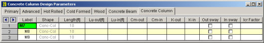
The following parameters can be defined for each concrete column.
The member Shape or Section Set is reported in the second column. This value is listed for reference only and may not be edited as it is dictated by the entry in the Section/Shape column on the Primary tab.
The member Length is reported in the third column. This value may not be edited as it is dependent on the member end coordinates listed on the Primary Data tab. It is listed here as a reference for unbraced lengths which are discussed in the next section.
You may specify unbraced lengths or have RISA-2D calculate them for you. The unbraced lengths are Lu-out and Lu-in.
The Lu values, Lu-out and Lu-in, represent the unbraced length of column members with respect to column type buckling out of plane and in plane, respectively. These Lu values are used to check the column for Euler buckling, and for the Moment Magnification Procedure in older editions of the ACI code.
If left blank these unbraced lengths all default to the member's full length.
For physical members, you can enter the code “Segment” in the unbraced length fields and the length of each segment will be used. A “segment” is the distance between the joints that are on the physical member. For example, suppose you have a physical member that is 20 feet in length, and there are two joints along the physical member, one 5 feet from the end and one at 15 feet. An unbraced length of 5 feet will be used for the first segment, then a value of 10 feet will be used in the middle segment, and again a value of 5 feet would be used in the last segment.
Note
For additional advice on this topic, please see the RISA Tips & Tricks website: www.risa.com/post/support. Type in Search keywords: Unbraced Lengths.
The K Factors are also referred to as effective length factors. K-out is for column type buckling out of plane and K-in is for buckling in plane.
If a value is entered for a K Factor, that value will be used for
RISA-2D is able to approximate the K-values for a column based on the member's sway condition and end release configuration. The K-factor approximation is based on the idealized tables given in the AISC steel specification. The following table gives the values used for various conditions.
| Table Case | End Conditions | Sidesway? | K-Value |
|---|---|---|---|
|
(a) |
Fixed-Fixed |
No |
.65 |
|
(b) |
Fixed-Pinned |
No |
.80 |
|
(c) |
Fixed-Fixed |
Yes |
1.2 |
|
(d) |
Pinned-Pinned |
No |
1.0 |
|
(e) |
Fixed-Free |
Yes |
2.1 |
|
(f) |
Pinned-Fixed |
Yes |
2.0 |
Note
RISA-2D will recognize a pinned boundary condition for the K approximation for a full pin, i.e. if all the rotations in the boundary condition are released. If any of the rotations in a boundary condition are restrained, the boundary condition is considered “fixed” for the K approximation.
Any configuration not described here will be given the default value of 1.0.
If any value that influences these K values is changed, the K approximation should be redone. For instance, if you have RISA-2D approximate K-values then change some end release designations, you should redo the K approximations.
Remember that the K-values are approximations, and you should check to make sure you agree with all K-values RISA-2D assigns. You can always override a K-value after an approximation by directly entering the value that you want in the appropriate field. Keep in mind that a subsequent approximation will overwrite any manually input values so you will need to override the approximation each time it is performed.
Limitation:
RISA-2D will currently neglect the influence of adjoining framing members when those members are connected at a joint that also has degrees of freedom restrained by boundary conditions. For example, suppose a column and beam member connect at a joint that is restrained for translation in both directions (I.e. the joint is “pinned”). The K factor approximation will neglect the beam member when it calculates the K factor for the column and vice versa. The effect will be that the ends of the members at that joint will be seen as “pinned” and not “fixed” for the K-factor approximation.
The Sway Flags indicate whether the member is to be considered subject to sidesway for bending in and out of plane. The Out sway field is for out of plane bending and the In sway field is for in plane bending. Click on the field to check the box and indicate that the member is subject to sway for that particular direction, or leave the entry blank if the member is braced against sway. These sway flags influence the calculation of the K Factors as well as the Cm.
The Cm Coefficients are used to check the column for Euler buckling, and for the Moment Magnification Procedure in older editions of the ACI code. Cm-out is for bending out of plane and Cm-in is for bending in plane. If these entries are left blank they will be automatically calculated.
In the ACI design code, the Cm values are only applicable for non-sway frames. Therefore, this value will be ignored if the corresponding sway flag is checked.
The user may choose to manually create the reinforcement layout for the column. This must be done if the user wishes to take advantage of bundled bars, multiple layers of reinforcement, or an unequal number of bars per face. See the section on the Concrete Database and Rebar Layouts for more information. If 'Default' is specified, then the program will design for an equal number of bars in each face of the rectangular column and may vary that reinforcing based on ACI minimums, maximums and the moment and shear demand at each section along the span.
The Icr Factor is used to reduce the bending stiffness of concrete columns per ACI 318-14 Table 6.6.3.1.1(a) (ACI 318-11 Section 10.10.4.1). If this entry is left blank, default values of 0.35 for beams and 0.70 for columns will be used.
Note
Due to cracking and material non-linearity, modeling the stiffness of concrete members is more complex than it is for steel or wood members.
For typical applications, ACI 318-14 Section 6.6.3.1 (ACI 318-11 Section 10.10.4) requires that member stiffness be reduced to account for the cracking that occurs when a member is subjected to ultimate level loads. As described in the previous section, RISA uses the Icr Factor to account for this stiffness reduction. However, for service level analysis, the level of cracking will be significantly less. Therefore, the stiffness used in your analysis should be representative of the reduced loading and reduced cracking. Per the ACI 318-14 Section R6.6.3.2.2 (ACI 318-11 Section R10.10.4.1), the program will account for this increased stiffness by applying a factor of 1.43 to the cracked section properties for any load combination that has the “Service Load” flag checked on the Design tab of the Load Combinations Spreadsheet.
Note
The Concrete Beam tab on the Members Spreadsheet records the design parameters for the code checks of concrete beams. These parameters may also be assigned graphically. See Modifying Member Design Parameters to learn how to do this.
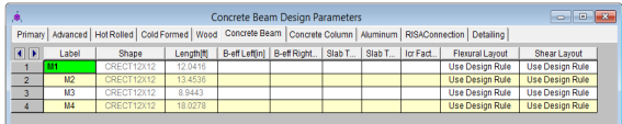
The following parameters can be defined for each concrete member.
You may assign a unique Label to all of the members. Each label
must be unique, so if you try to enter the same label more than once you
will get an error message.
The member Shape or Section Set is reported in the second column. This value is listed for reference only and may not be edited as it is dictated by the entry in the Section/Shape column on the Primary tab.
The
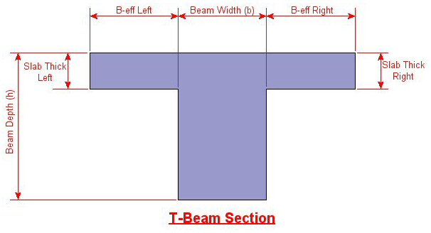
B-eff Left and B-eff Right are the effective widths of the slab for T-beam and L-beam design. See the section on T-beam & L-beam Sections below for more information on Effective widths.
The user may choose to manually create the reinforcement layout for the beam. This must be done if the user wishes to take advantage of compression steel, or multiple layers of reinforcement. See Concrete Database - Rebar Layouts for more information. If Use Design Rule is specified, then the program will design for one layer of reinforcing and may vary that reinforcing based on ACI minimums, maximums, and the moment and shear demand at each section along the span using the Member Design Rules as the parameters of the reinforcement selection. If you define your own rebar layout, and compression reinforcement is defined, then the program will consider the compression reinforcement in the analysis.
The Icr Factor is used to reduce the bending stiffness of concrete beams.
For ACI and Canadian codes (ACI 318-14 Section 6.6.3.1 and A23.3-04 section 9.2.1.2), if this entry is left blank, the Icr factor will default to a value of 0.35 for beams and 0.70 for columns.
For Australian and New Zealand codes (per section 6.6.2 of AS3600-2001), this will default to a value of 0.4 for beams and 0.8 for columns.
For Indian and Saudi codes, this entry will default to a value of 1.0 for beams and columns.
Note
Due to cracking and material non-linearity, modeling the stiffness of concrete members is more complex than it is for steel or wood members.
For typical applications, ACI 318-14 Section 6.6.3.1 (ACI 318-11 Section 10.10.4) requires that member stiffness be reduced to account for the cracking that occurs when a member is subjected to ultimate level loads. As described in the previous section, RISA uses the Icr Factor to account for this stiffness reduction. However, for service level analysis, the level of cracking will be significantly less. Therefore, the stiffness used in your analysis should be representative of the reduced loading and reduced cracking. Per ACI 318-14 Section R6.6.3.1.1 (ACI 318-11 Section R10.10.4.1), the program will account for this increased stiffness by applying a factor of 1.43 to the cracked section properties for any load combination that has the “Service Load” flag checked on the Design tab of the Load Combinations Spreadsheet.
Note
T-beams and L-beams may be specified by assigning effective slab widths and slab thicknesses for the left and right side of the beam on the Concrete Beam tab of the Members Spreadsheet. These modifications may also be made graphically via the Modify Properties tab of the Draw Members tool.
RISA-
If the values of either B-eff Left or B-eff Right are left blank, a value of zero will be assumed, indicating no additional slab width beyond 1/2 the beam width on that side.
Note:
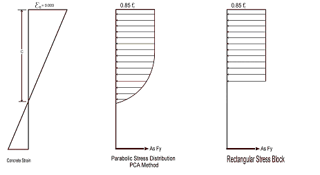
You can specify whether you want your concrete design to be performed with a rectangular stress block, or with a more accurate parabolic stress block. While most hand calculations are performed using a rectangular stress block, the parabolic stress block is more accurate. In fact, most of the PCA design aids are based upon the parabolic stress distribution. A good reference on the parabolic stress block is the PCA Notes on ACI 318-99.
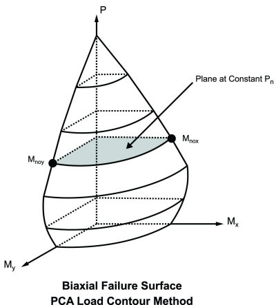
You can specify whether you want your column design to be performed by using Exact Integration, or by using the PCA Load Contour Method. While most hand calculations are performed using the Load Contour Method, this method is merely an approximation based on the uniaxial failure conditions and the Parme Beta factor. In contrast, the Exact Integration method uses the true biaxial strain state to design the member. A good reference on the Load Contour Method is chapter 12 of the PCA Notes on ACI 318-99.
αct= 1 (assumed in Eq 3.16)
η1= η2=1 (assumed in Eq 8.2 to calculate bond stress)
λ3, λ5, λ4=1 (assumed in Eq 8.4)
Cd in Table 8.2 assumed to be 1 bar diameter rebar spacing
Development length when hooks are provided uses same assumptions as BS 8110-1: 1997
To compute the shear capacity of concrete the following recommended values are being used:
CRd,c =0.18/γc for Eq 6.2.a
vmin =0.035 k3/2 fck1/2
ν =.6*[1- fck /250]
Vmax is calculated from Eq. 6.5.
θ is assumed 45 degrees in Eq 6.8.
Biaxial column design done using Eq. 5.39
λlim = 20 A B C/n1/2 (A=.7, B= 1.1, C=0.7 for unbraced)
Kϕ =1 in Eq 5.34; the effect of creep is neglected.
Torsion –
Beams
Creep / Long Term Deflections – No considerations are taken in the analysis to account for the effects of creep or long term deflections.
Beam Design
– Beams are not designed for
weak axis y-y bending, weak axis shear, or axial forces. A message
is shown in the detail report to remind you of this.
Column Design – Columns with biaxial moment and no axial load will currently be designed using the PCA Load Contour Method even if Exact Integration is selected on the Model Settings dialog. This is shown on the detail report.
Shear Design –When ACI 318-19 is selected, the shear strength of concrete (Vc) uses equations in Table 22.5.5.1. Note that for members meeting the minimum shear reinforcement requirement (Av≥Av,min), Vc is taken as the larger of the results calculated by the equations (a) and (b) in the table. ACI 318-19 code suggests ρw may be taken as the sum of the areas of longitudinal bars located more than two-thirds of the overall member depth away from the extreme compression fiber. Therefore, RISA calculates ρw as the sum of the areas of longitudinal bars on the tension face.
When other ACI 318 editions are selected, the shear strength of the concrete alone is limited to the standard 2*λ*sqrt (f'c) equation from ACI 318-14 Section 22.5.5.1 (ACI 318-11 Section 11.2.1.1) and does not use the more detailed calculations of ACI 318-14 Table 22.5.5.1 (ACI 318-11 Section 11.2.2). Also, note that for members with significant axial tension (greater than 0) the program designs the shear reinforcement to carry the total shear per ACI 318-14 Section R22.5.7.1 (ACI 318-11 Section 11.2.1.3).
Deep Beam Design – The program does not design deep beams as defined in ACI 318-14 Section 9.9.1.1(a) (ACI 318-11 Section 10.7).
Concrete Stress Profile – Concrete stress strain curve (parabolic) is assumed same as PCA method for the Canadian codes.
Bi-Axial Bending - The program uses the simplified uniaxial solution provided in the Canadian specification rather than performing a complete biaxial condition.
Mid-Depth Flexural Strain for Shear Design - The program uses the code equation (per the General Method) to calculate exwith the moment and shear at the section taken from the envelope diagrams. The maximum ex for each span is conservatively assumed for the entire span. Currently the program has no option for pre-stressing, so Vp and Ap are both taken as zero.
Shear Design - The shear strength of concrete is calculated using β and θ, which are both calculated per the General Method (Clause 11.3.6.4 from the 2004 CSA A23.3). Sze is calculated per equation 11-10 and ag is always assumed to equal 20 mm (maximum aggregate size).
Concrete Stress Profile – Concrete stress strain curve (parabolic) is assumed same as ACI for the New Zealand and Australian codes.
Neutral Axis Parameter – Ku in AS code is always assumed to be less than 0.4.
Rebar Spacing – NZS and AS codes: max spacing of rebar (beam) is 300 mm and minimum spacing is one bar diameter or 25mm whichever is bigger.
Shear Strength in Beams – In AS code, when calculating the shear strength of a beam β2, β3 are always assumed to be unity. This is always conservative for beams will little axial load, or beams in compression. But, may be unconservative for members subjected to significant net tension.
Bi-Axial Bending – The New Zealand code does not appear to give a simplified method for solving biaxial column design. Therefore, the PCA load contour method is being used instead.
Shear Tie Spacing – Column/beam shear tie spacing is based on (a) and (c) of NZS 9.3.5.4 :1995.
Development Length – Development length in NZS is based on NZS 7.3.7.2 where αa is conservative assumed to be 1.3 (top bars) for all cases. For the AS code, it is assumed that K1=1 and K2=2.4 in clause 13.1.2.1 of AS 3600:2001.
Slender Column Calculations – EI is assumed to be equal to 0.25EcIg (with βd =0.6) in slender column calculations in AS and NZS codes (like in ACI).
Concrete Stress Profile – Concrete stress strain curve (parabolic) is taken from the British specification.
Cracked Sections – Icracked defaults to 1.0 for the British code. But, a user entered value may be entered if desired. Service level stiffness is assumed to be 1.43 times the strength stiffness, but is not allowed to exceed Igross.
Bi-Axial Bending – The program uses the simplified uniaxial solution provided in the British specification rather than performing a complete biaxial condition.
Concrete Stress Profile – Concrete stress strain curve (parabolic) is taken from the EuroCode specification.
Cracked Sections – Icracked defaults to 1.0 for EuroCode. But, a user entered value may be entered if desired. Service level stiffness is assumed to be 1.43 times the strength stiffness, but is not allowed to exceed Igross.
Bi-Axial Bending – The program uses the simplified uniaxial solution provided in the EuroCode rather than performing a complete biaxial condition.
Concrete Stress Profile – Concrete stress strain curve (parabolic) is taken from the Indian specification.
Cracked Sections – Icracked defaults to 1.0 for the Indian code. But, a user entered value may be entered if desired. Service level stiffness is assumed to be 1.43 times the strength stiffness, but is not allowed to exceed Igross.
Bi-Axial Bending – The program uses the simplified uniaxial solution provided in the Indian specification rather than performing a complete biaxial condition.
Concrete Stress Profile – Concrete stress strain curve (parabolic) is assumed to be the same as the ACI code.
Shear Strength– The shear strength is based on 11.3.1.1 and does not include the more detailed provisions of section 11.3.1.2.
Yield Strength of Shear Ties - The yield strength of shear ties is not allowed to exceed 420MPa.
Shear Tie Spacing - Minimum spacing of shear ties is set to 50mm
Bi-Axial Bending – Both the Exact Integration and the PCA Load Contour methods for bi-axial bending are supported in the Saudi code.
In some instances code checks are not performed
for a particular
Certain very short spans in physical members can end up with less than 5 design sections. No design is attempted without at least 5 sections because maximum values may be missed and an un-conservative design may result.
Certain very short spans in physical members can end up with lengths less than 1 foot. No design is attempted for these sections.
Under older ACI codes slender sway members need to be run with the P-Delta option turned on to account for secondary forces and moments. In some situations, a preliminary design without P-Delta is useful and so a design is performed and this warning is shown to remind you to run the final analysis including P-Delta effects. Alternately, if you’re using the redesign feature, the next suggested column may resolve this issue if it’s not slender.
Since RISA-2D allows you to specify a starting column size, it’s possible that for slender columns under substantial axial load you'll exceed the critical buckling load used in the slenderness equations in ACI 318-14 Section 6.6.4.5.2 (ACI 318-11 Section 10.10.6). Design results are still shown so the suggested shapes can be used to pick a new suggested column size that will not have this problem. Note that the design results shown are NOT valued because the slender moment effects have NOT been considered.
Members that violate the KL/r limit still have
design results calculated and shown.
This message is shown when you've requested the Exact Integration option on the Model Settings Dialog, but we weren't able to converge a solution for the column in question. When Exact Integration does not converge, the PCA Method is used instead to give an idea of the demand vs. the capacity.
One of the limitations of the PCA Method is that it requires the column being checked to have a greater axial capacity than the axial demand. Since RISA-2D allows you to set a starting size, it’s possible that the demand may be greater than the capacity. In this case a very rough estimate of the capacity is calculated by using the independent moment capacity about each axis considering the axial load. The resulting code check value is then based on the combined demand vector over the combined capacity vector and will always be greater than 1.0. The purpose of the results in this case is to show the column failed, not to give an accurate estimate of the over-demand. The redesign feature will suggest a larger shape to resolve this issue.
This warning is stating that either minimum spacing or strength requirements are not being met for the shear reinforcement in the concrete member.
A second order analysis is required as of the 2014, 2011 and 2008 editions of the ACI 318 code. A code check will only be given if P-Delta is turned on in the Load Combinations spreadsheet, or if this requirement is intentionally waived in the Application Settings.